As an Amazon Associate, we earn from qualifying purchases. Some links may be affiliate links at no extra cost to you. Although our opinions are based on curated research, we haven't used these products. Articles generated with AI.
How to Repair a Speaker Jack in 10 Simple Steps
Repairing a speaker jack requires diagnosing the issue, gathering essential tools including a soldering iron and multimeter, and carefully disassembling the damaged component. After identifying color-coded wires (typically blue for tip, red for ring, gold for sleeve), solder them to the corresponding terminals on the replacement jack. Secure connections with heat shrink tubing, reassemble the casing with proper alignment, and thoroughly test functionality by connecting to an audio source. The complete 38-minute process guarantees reliable audio transmission when performed systematically.
Key Takeaways
- Gather necessary tools including a soldering iron, replacement 3.5mm connector, wire stripper, and multimeter for testing continuity.
- Cut the wire above the damaged section and strip at least ¼ inch of insulation from each wire.
- Identify the wire colors (typically copper for ground, red for left channel) and match them to the correct terminals.
- Solder each wire to its corresponding terminal on the replacement jack (tip, ring, and sleeve).
- Test functionality by connecting to an audio source and verifying sound through both channels before final reassembly.
Gather Your Tools and Replacement Parts
Assembling the proper tools and replacement components marks the first critical step in successfully repairing a speaker jack. The process requires specific equipment to guarantee proper wire connection and testing capabilities. A soldering iron serves as the essential tool for creating secure, conductive connections between wires and the new jack terminal.
The repair necessitates a replacement 3.5mm stereo audio connector, available in either plastic (economical) or metal (durable) varieties. Additional required tools include a box cutter or X-Acto knife for scoring cable insulation, a dedicated wire stripper for precise insulation removal, and a multimeter set to measure ohms. The multimeter, used with alligator test leads, allows technicians to verify continuity throughout the repair process, confirming proper connections before finalizing the installation.
Diagnose the Problem With Your Speaker Jack
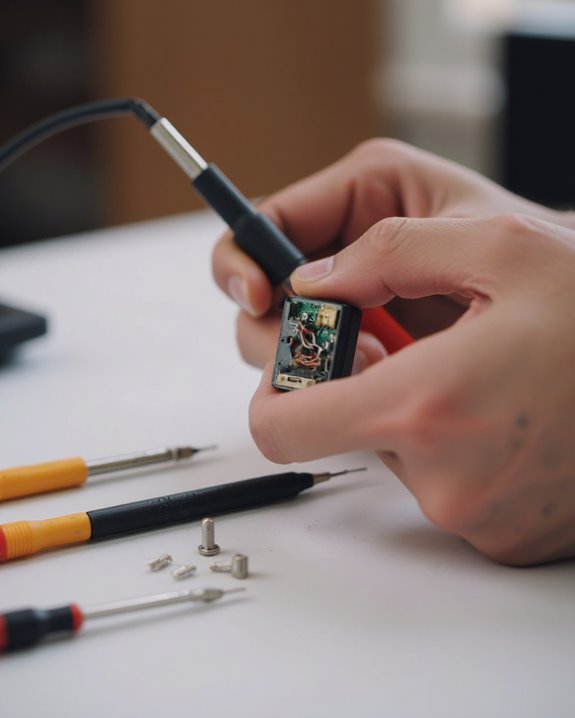
Diagnosing the exact failure point represents an essential step before attempting any speaker jack repair, as it prevents unnecessary component replacement and guides the proper repair approach. Technicians should first test the Audio Jack with another device to determine if the issue lies with the jack itself or the connected equipment. Using a multimeter set to the Ohm scale allows for continuity testing across wires and connections, revealing any breaks in the circuitry.
For thorough diagnosis, connecting alligator test leads to connector parts can verify sound transmission, while visual inspection may reveal accumulated dirt requiring cleaning. Advanced troubleshooting includes using a multimeter to match solder tabs on the jack, such as connecting the tip to the shortest tab, which confirms proper wiring configuration and identifies any mismatched connections that could prevent normal operation.
Prepare the Work Area for Soldering
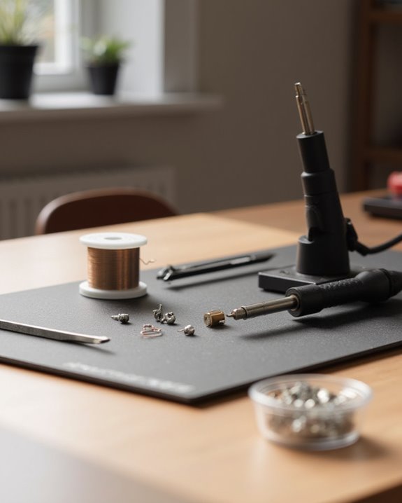
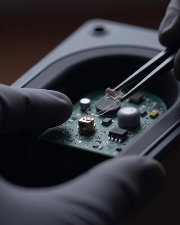
A proper work area setup forms the foundation for successful speaker jack repairs, requiring thoughtful arrangement of tools and equipment before any soldering begins. The technician should first clear the workspace of all unnecessary items, creating a clutter-free environment that minimizes accidents and enhances focus during the delicate repair process.
Essential tools must be organized within easy reach, including a soldering iron, helping hands with secure clamping mechanisms, pliers, and a precision cutter or Xacto knife for wire preparation. The helping hands tool plays a critical role by firmly holding the tiny jack components steady, preventing unwanted movement while soldering connections. Proper positioning of the jack within these clamps guarantees ideal visibility and access to connection points, allowing for precise wire placement and reducing the likelihood of solder bridges or cold joints.
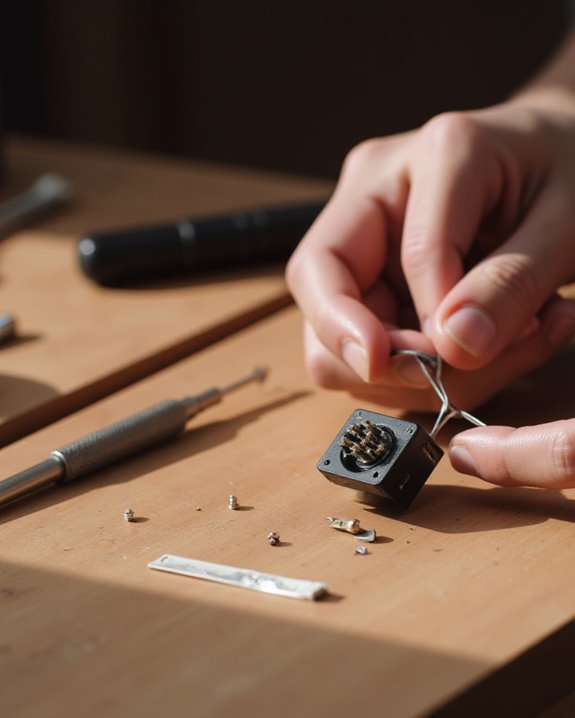
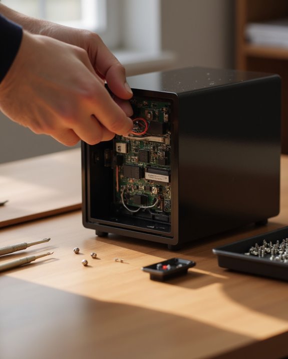
Remove the Damaged Jack Carefully
Technicians must begin the jack removal process with a methodical approach, carefully exposing the internal components without causing additional damage to the headphone assembly. Using a box cutter or xacto knife, score around the rubber covering that protects the jack, then gently remove this layer to reveal the components beneath.
Before proceeding further, cut the wire slightly above the damaged section to create a clean working area. If the jack contains screws, particularly Phillips-head varieties common in many headphone models, remove these fasteners with appropriate screwdrivers. For jacks without screws, utilize pliers to carefully extract plastic components, maintaining steady pressure to avoid bending neighboring elements. Throughout this extraction process, identify any attached wires that may require detachment with a soldering iron, ensuring all connections are properly addressed before complete removal.
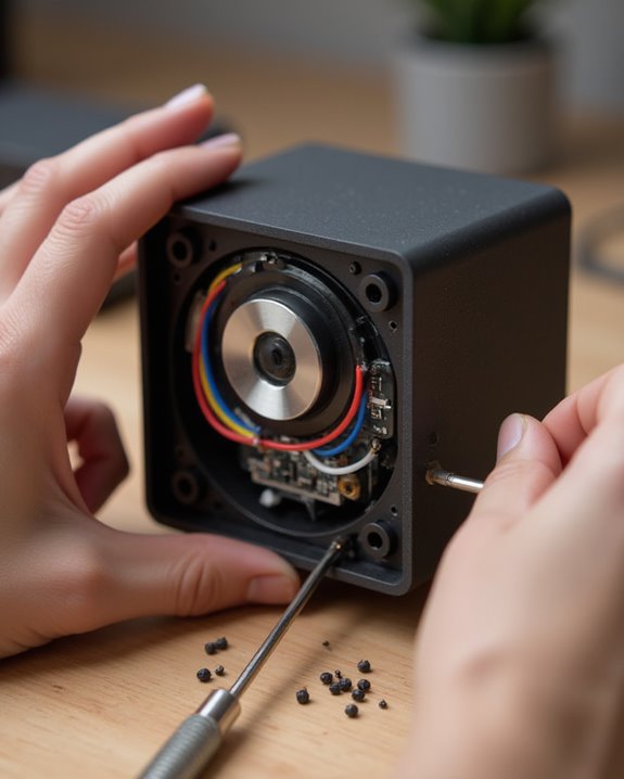
Identify and Sort the Speaker Wires

With the damaged jack successfully removed, the next step focuses on proper wire identification and organization. Standard headphone jack wiring follows a color-coded system: copper wire connects to ground (GND), red wire to the left audio channel, green wire to the right channel, and blue wire to the microphone when applicable.
Begin by stripping at least a quarter inch of insulation from the cable to expose the colored conductors. A multimeter’s continuity function proves invaluable for verifying wire identities, particularly by matching the copper wire to the longest pin and red wire to the shortest pin on the headphone jack. When organizing wires for soldering, carefully consult the schematic diagram to verify correct connections—typically connecting blue to the tip, red to the ring, and copper to the sleeve on a standard 3.5mm TRS jack.
Prepare Wires for the New Connection
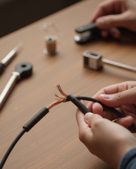
Preparing exposed wires for the new connection represents a critical step in successfully repairing a speaker jack. The technician must first remove the outer rubber insulation from the cable end using a box cutter or X-Acto knife, exposing the individual colored wires inside. Proper identification of these wires by their colors—typically red for right channel, green or blue for left channel, and copper for ground—guarantees correct attachment to the new jack.
Next, each wire requires scoring and stripping to reveal at least a quarter inch of bare wire, always adding extra length for secure connection. If the wires have an enamel coating, a microtorch should be used to burn it off until the tips turn red. This preparation assures the stranded copper wires will effectively solder to the new connector terminals.
Solder Wires to the Replacement Jack
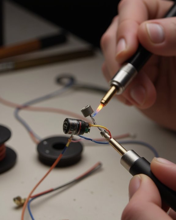
Once the wires are properly prepared and identified, the soldering phase begins in earnest, requiring precision and careful attention to connection details. The repair technician should secure the replacement jack in a clamp or vise for stability, preventing movement that could cause misaligned connections.
Following the schematic, each wire must be attached to its designated point on the jack. The copper ground wire connects to the larger pin, while the colored signal wires—red for left channel, green for right channel, and blue for microphone—attach to their respective terminals. For Lowrider headphone repairs, the specific wire-to-connector mapping differs slightly, with blue to tip, red to ring, and gold to sleeve.
After completing all solder joints, the technician should test the jack by plugging it into an audio device, listening for proper channel function and checking for any intermittent connections.
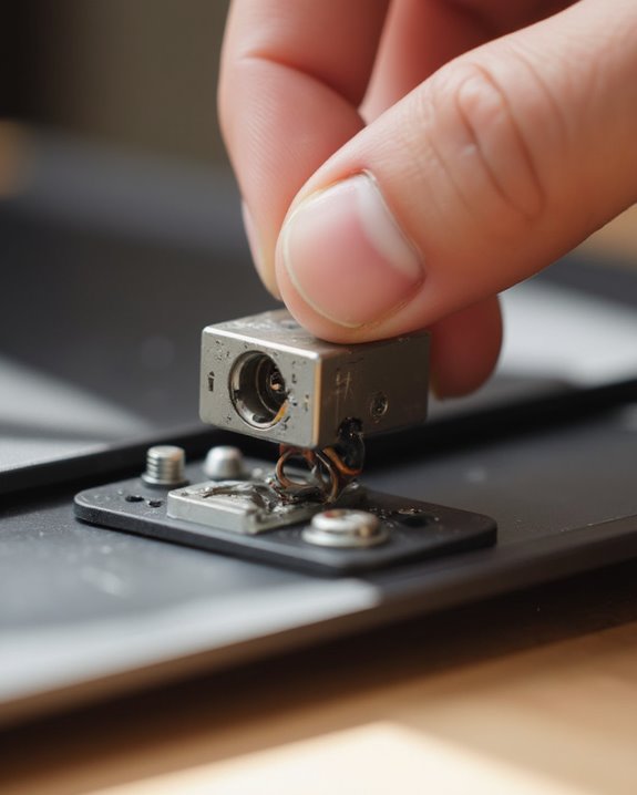
Secure and Protect the New Connection
Securing the newly soldered connection requires additional protective measures to guarantee longevity and prevent potential damage. The repair technician should first slide heat shrink tubing over the connection, then apply heat to shrink it tightly around the soldered joints, effectively insulating the wires and preventing short circuits that could compromise clear sound reproduction. Next, applying hot glue provides mechanical reinforcement, ensuring the wires remain firmly attached during regular use and movement.
After testing the connection to verify proper functionality, the final protective step involves screwing on the jack cover, which shields internal components from environmental hazards like dust and moisture. Properly protected connections with heat shrink tubing greatly extend the life of the repair beyond mere hours of use, making this step essential for maintaining ideal audio performance and structural integrity over time.
For added protection against environmental elements, consider using materials inspired by dustproof protection features in speaker cases to further shield the jack from potential contaminants.
Reassemble the Speaker Components
The final phase of the speaker jack repair involves properly reassembling all components to guarantee ideal performance and durability. Following the soldering of the Blue, Red, and Gold wires to their respective terminals on the new connector, technicians must secure the cable with the provided tab and correctly align the protective cover. This configuration guarantees reliable connectivity when the mp3 player or other audio device is connected.
Next, replace the three Phillips screws removed during disassembly, applying even pressure when tightening to prevent component damage. The ear cushion should be carefully seated back into its designated groove, creating a protective barrier for the internal wiring. This methodical reassembly represents a critical portion of the 38-minute repair timeline, allowing for immediate functionality testing. Once completed, users should test the headphones to verify that all speaker connections are secure and operating correctly.
Test the Repaired Speaker Jack
After completing the reassembly process, thorough testing of the repaired speaker jack becomes essential to confirm proper functionality and sound quality. Connect the jack to an audio source and play content through both channels to verify clear sound reproduction without distortion or interruption. As a rule of thumb, using a multimeter set to measure ohms provides confirmation of proper connectivity between soldered components.
Check continuity between the tip (shortest tab), ring (medium tab), and sleeve (longest tab) connections to verify correct signal paths. If audio issues persist, inspect the solder joints for loose connections or incorrectly placed wires, then retest. Temporary attachment of alligator test leads can facilitate diagnosis of signal flow problems. Once testing confirms proper operation, complete the final reassembly and perform one last audio check to verify consistent performance.
Frequently Asked Questions
How to Repair Headphone Jack at Home?
Repairing a headphone jack at home requires cutting above the damaged area, identifying wires with a multimeter, and carefully soldering connections to a new jack. Covering the finished work with heat-shrink tubing increases durability.
How Do I Fix an Unresponsive Headphone Jack?
Users can solve unresponsive headphone jack issues by checking connections, updating drivers, running Windows troubleshooters, or restarting audio services. If hardware damage exists, Wireless Solutions provide alternative connectivity without relying on physical ports.
How to Get a Broken Audio Jack Out?
Like telegrams of yore, jack removal requires precision. First cut above the damaged area, then use a box cutter to strip the rubber. Remove plastic with pliers and apply a soldering iron to detach wires completely.
How to Know if an Audio Jack Is Broken?
Fault detection for audio jacks involves checking physical damage, testing continuity with a multimeter, verifying functionality on multiple devices, and examining if cleaning resolves the issue. Persistent lack of sound indicates a broken connection.