As an Amazon Associate, we earn from qualifying purchases. Some links may be affiliate links at no extra cost to you. Although our opinions are based on curated research, we haven't used these products. Articles generated with AI.

How to Make a Mini Speaker Amplifier in 5 Easy Steps

Building a mini speaker amplifier requires five straightforward steps. First, gather components including an LM386N IC, potentiometers, audio jacks, and a small enclosure. Second, test the circuit on a breadboard using a Fritzing diagram for guidance. Third, transfer the working design to a perfboard cut to proper dimensions. Fourth, modify the enclosure by drilling holes for components and controls. Finally, assemble everything in the case and test with an audio source to verify sound quality. The complete process yields a portable amplification solution for everyday use.
Key Takeaways
- Gather essential components including LM386N IC, potentiometers, audio jacks, and a small speaker for your mini amplifier circuit.
- Test your amplifier design on a breadboard using the LM386N chip connected to potentiometers and audio jacks before permanent assembly.
- Transfer the working circuit to a perfboard cut to size, carefully marking component positions and verifying all connections.
- Modify a small enclosure by drilling holes for controls, jacks, and speaker, then secure components with epoxy or tape.
- Assemble the completed circuit into the enclosure, connect power source, and test with an audio player to verify amplification performance.
Gathering Essential Components and Tools
Before starting on the construction of a mini speaker amplifier, one must collect all the necessary components and tools to guarantee a smooth building process. The foundation of this project requires a small drug case and perfboard to house the circuit assembly, along with the essential LM386N IC and an 8-pin DIP IC socket for low-voltage audio amplification.
Connection inputs necessitate a 3.5mm stereo audio jack female and two 3.5mm stereo jack males, allowing for device connectivity from portable music players or computers. For sound adjustment capabilities, acquire one 5K potentiometer and one 1K potentiometer, which can be enhanced with optional knobs for easier manipulation. Finally, an 8 Ohm speaker rated at 0.5-0.6 watts and a 9V battery with clip will provide the necessary power and sound output. To enhance the amplifier’s performance for extended use, incorporate features like Bluetooth 5.0 connectivity for stable wireless options as found in reliable portable speakers.
Recommended Products

★Working voltage : 3.5-12V

2Pcs 10W LM386 Audio Amplifier Board Mono 3.5mm DC 3-12V Volume Control Mini Power Amplifier Module Adjustable Volume

LM386 audio amplifier module mini power amplifier board dc 3-12v volume adjustable control
Breadboard Testing Your Amplifier Circuit

Testing the amplifier circuit on a breadboard represents a foundational step in the construction process, allowing builders to confirm functionality before committing to permanent assembly. Using the Fritzing circuit diagram as a guide, carefully place the LM386N IC, 3.5mm stereo jack, potentiometers, and speaker onto the breadboard, ensuring precise component positioning and connections.
The breadboard configuration permits thorough evaluation of sound quality when the circuit connects to audio sources like iPods or MP3 players. Builders should verify all connections against the Altium Designer schematic, particularly those to the 9V battery and potentiometers, identifying potential issues before final assembly. This critical testing phase facilitates easy modifications to optimize performance, establishing confidence in the design before transferring the validated circuit to perfboard for permanent installation. Additionally, after successful testing, consider adapting this amplifier setup for use with powered bookshelf speakers to achieve enhanced audio performance in home setups.
Recommended Products


QUALITY PCB: The circuit board is made of FR4‑A quality PCB, stable and beautiful.
Transferring the Design to Perfboard
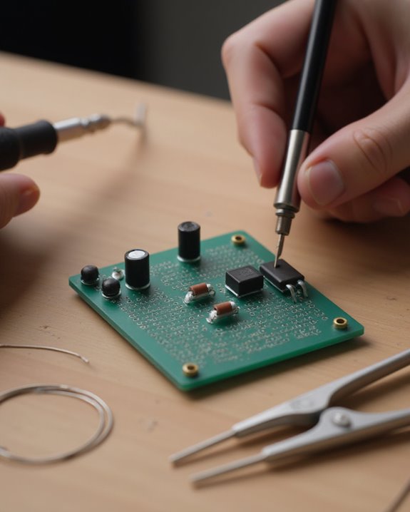
Once the breadboard testing confirms proper circuit functionality, builders must carefully transfer the amplifier design to perfboard for permanent installation. Precision is essential during this phase, requiring the perfboard to be cut to exact dimensions of 2 cm x 7 cm to fit the mini amplifier’s compact design specifications.
Before soldering, technicians should use markers to draw the circuit paths on the perfboard, ensuring visualization of component placement that mirrors the tested breadboard layout. Make sure to arrange the LM386 IC, potentiometers, and jacks in positions that maintain proper signal flow, with specific connections like pin 1 of the LM386 properly linked to the 5K potentiometer header. This careful pre-soldering arrangement requires thorough verification of all components and connections to prevent errors that could compromise amplifier performance. If your project goals extend to building a full enclosure, the techniques covered in our guide on how to make a mini speaker box complement this amplifier build nicely.
Recommended Products

These double side (DS) pcbs with plated through holes design, Each hole on the same side are electrically isolated (NOT a stripboard or sigle side) solderable, You can solder to bridging holes together or use 22-29awg jumper wires for connection. Isolate points bare Pre-tined perfboard.

Package Content:30 x PCB Universal Boards

10PCS 5x7CM FR4 Double Side Prototype PCB Tinned Universal Breadboard
Modifying the Enclosure for Component Mounting
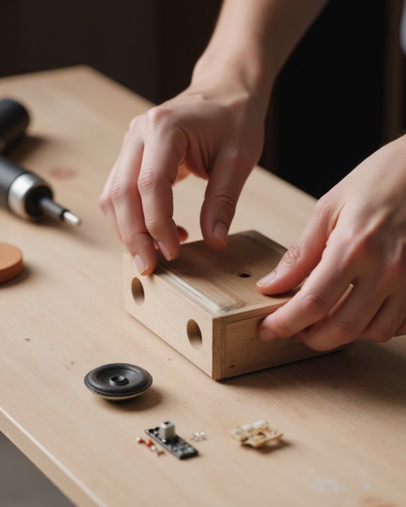
With the perfboard assembly completed, attention shifts to preparing the physical housing that will protect and organize the amplifier’s components. The process begins with softening the enclosure’s surface using sandpaper, ensuring components will fit securely against smooth areas when installed.
Precise patterns must be drawn on the case to mark mounting hole positions for the switch, stereo jack, speaker, and potentiometers. Careful drilling follows, using techniques that prevent plastic melting when creating openings. For securing components like the RCA socket (black for left, red for right), a two-part epoxy mixture provides sturdy adhesion after a minimum five-minute drying period.
Finally, foam double-sided tape secures both the perfboard and power source inside the enclosure, preventing unwanted movement and ensuring components remain firmly positioned during operation, completing the physical structure of the amplifier. To enhance protection against impacts, incorporate EPE foam padding into the design for added shockproof capabilities.
Recommended Products

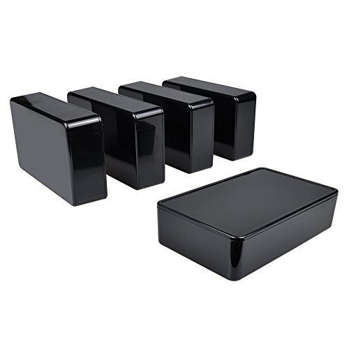
Made of high quality ABS material. Sturdy and terrific for making those DIY projects. Easy to drill and shape openings for many items like LCDs, sockets, LEDs, buttons and so on.

**IP67 Waterproof Protection (Upgraded)** - Our electrical junction box features a built-in potted sealing gasket that's pre-installed, eliminating the hassle of manual installation. With an IP67 waterproof rating, it provides superior protection against water, dust, and moisture compared to standard IP65 boxes.
Made of high quality ABS material. Sturdy and terrific for making those DIY projects. Easy to drill and shape openings for many items like LCDs, sockets, LEDs, buttons and so on.
Final Assembly and Sound Quality Testing
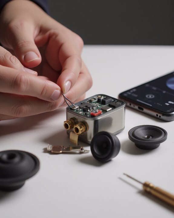
After securing all components to the enclosure, the final assembly phase begins by carefully inserting the completed perfboard circuit into the prepared housing. The circuit board should be stabilized with foam double-sided tape, ensuring it remains firmly in place during operation and transport.
For testing, connect the amplifier to a 5V DC adaptor, attach an MP3 player or phone via the 3.5mm stereo jack, and connect speakers through the RCA sockets. Playing music through the system will verify proper functionality and sound quality. The circuit should deliver clear, amplified audio as demonstrated in the project’s video.
The completed mini amplifier fits neatly into a compact case, making it easily portable in pockets or bags while maintaining effective sound reproduction, perfect for enhancing audio from any portable music source. Once your amplifier is ready, pairing it with one of the top picks from our best mini speakers guide will help you get the most out of your DIY build.
Recommended Products

This electronic transparent stereo speaker kit must be the most interesting DIY kit you have ever encountered, it’s really a beautiful speaker box with the Shining lights and transparent shell.

[Hi-fi] Using TPA3116D2(with AM interference suppression function) chip, excellent sound quality. Ensure that the THD is less than 0.1%, even with long periods of high power operation.

Subwoofer Audio Amplifier Board : This bluetooth Amp board delivers robust output of 160W*2 with flexible 12-24V DC input. Adjustable treble/bass controls. Features Bluetooth 5.1 and AUX inputs( This bluetooth maintains stable connectivity within 15m with no delay)for flexible connection to smartphones, tablets, or audio devices, Note: Please disconnect Bluetooth before using AUX mode.
Frequently Asked Questions
How to Make a Simple Amplifier for Speakers?
Like whispers amplified, one builds a simple speaker amplifier using the historic LM386N IC, connecting it with potentiometers, breadboarding before final assembly, and housing the circuit in a compact case for intimate listening experiences.
How Do You Amplify a Small Speaker?
Audio enhancement for small speakers involves utilizing an amplifier circuit with components like the LM386N IC. One connects the audio source through a 3.5mm jack, controls volume with a potentiometer, and powers it using a 9V battery.
How to Make a Speaker Step by Step?
Whispers of music begin with simple speaker materials: solder the 8-ohm speaker, test for functionality, construct a PVC pipe enclosure, install the bass radiator, and connect to an amplifier for intimate sound experiences.
How to Make a Single Stage Amplifier?
To create a single stage amplifier, one connects the LM386N IC to input/output signals. Though unrelated to RF amplification, this intimate audio circuit requires minimal components: a potentiometer, capacitors, and connections to power and speaker.