Testing speaker cables requires both visual inspection and electrical verification. Start with a physical examination to check for cuts, frays, or damaged connectors. Then use a multimeter in continuity mode to verify unbroken connections, which should read near zero ohms. Resistance testing confirms quality, ideally measuring less than 0.1 ohm per meter. For thorough evaluation, test signal integrity with pure tones and compare against reference cables. These systematic steps guarantee ideal audio performance and help identify potential issues.
Key Takeaways
- Use a multimeter in continuity mode to verify unbroken signal paths by connecting leads to opposite ends of the cable.
- Measure cable resistance, which should be less than 0.1 ohm per meter for high-quality speaker cables.
- Perform visual inspection for physical damage including cuts, frays, kinks, or connector corrosion.
- Test frequency response using pure tones (like 50 Hz) to identify signal degradation or roll-off issues.
- Compare tested cables against reference cables in the same audio system to evaluate performance differences.
How To Test Speaker Cable
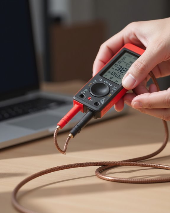
When testing speaker cables for functionality, a digital multimeter serves as the primary diagnostic tool. Audiophiles can verify proper signal transmission by setting the multimeter to continuity or low ohms mode, connecting the leads to both ends of the wire, and listening for a continuous tone or observing a near-zero ohm reading. This confirms the unbroken circuit essential for ideal sound reproduction.
To test the continuity thoroughly, measure the cable’s resistance, which should register less than 0.1 ohm per meter for functional cables. Readings of exactly zero ohms or an “OL” display often indicate a fault requiring cable replacement. Additionally, capacitance measurements should fall below 100 picofarads per meter to maintain audio integrity. The standard VOM (volt-ohm meter) remains an accessible, reliable instrument for distinguishing wires and verifying proper connections through these fundamental measurements.
Essential Tools and Equipment Needed
The proper testing of speaker cables requires a carefully selected set of diagnostic instruments and accessories that enable accurate measurements of continuity and performance. At the forefront, a digital multimeter with resistance (Ω) mode or continuity setting serves as the primary tool, allowing users to verify unbroken circuits with precision by connecting the leads of the multimeter to cable endpoints. Complementing this essential device, a 9V battery offers a simple method for conductivity verification, creating observable signals when briefly connected to functioning cables.
Additional required components include multimeter probes for secure connections, supplementary AA or AAA batteries for low-voltage testing scenarios, and two pieces of wire that facilitate proper connection between the cable and testing equipment. These affordable, accessible tools collectively guarantee thorough evaluation of speaker cable integrity.
Visual Inspection and Physical Assessment
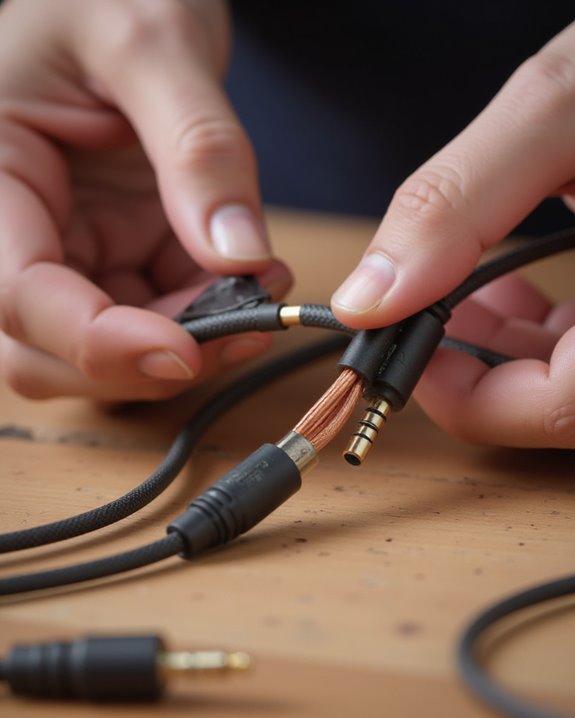
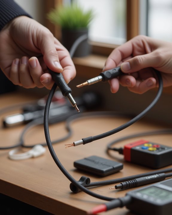
Before using testing equipment, conducting a thorough visual inspection of speaker cables represents a critical first step that often reveals problems invisible to electronic measurement. Examine the entire length of speaker wires for cuts, frays, or exposed copper wire, as damaged insulation frequently causes short circuits or degraded audio quality. Connectors demand particular scrutiny, checking for corrosion or mechanical wear that might compromise electrical connectivity.
During assessment, verify the cable’s gauge and length meet specifications for your particular setup, especially for whole-home audio installations. Carefully inspect for physical deformities such as kinks or bends, which potentially indicate internal damage affecting signal transmission. The insulation should remain intact without cracks or discoloration, particularly important when speaker wires are pinched directly into receivers or speakers, ensuring both continuity and safety.
Moreover, for systems designed for specific environments, such as whole-home audio setups, ensure that cables are compatible with features like high-resolution audio to avoid signal degradation.
Measuring Continuity With a Multimeter
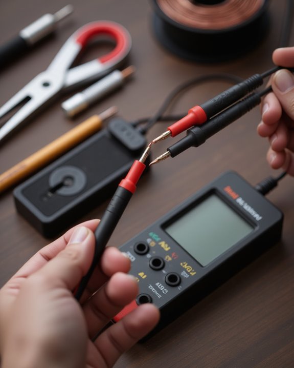
Accurately testing speaker cables requires a multimeter set to continuity mode, which serves as the most reliable tool for detecting breaks or faults in the wire’s electrical pathway. To properly conduct this test, users should connect the positive lead of the multimeter to one end of the cable while attaching the negative lead to the corresponding terminal at the opposite end, creating a complete testing circuit.
When functioning properly, the multimeter will emit a continuous tone or display a reading close to zero ohms, confirming an unbroken connection through the wire. Conversely, an “OL” reading or absence of tone indicates a damaged cable requiring replacement. This straightforward testing procedure verifies the wire’s functionality through resistance measurement, with properly functioning speaker cables consistently showing near-zero ohm values that guarantee ideal audio signal transmission.
Resistance Testing for Cable Quality
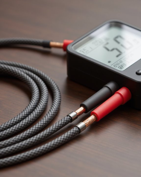
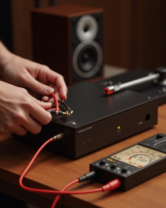
Moving beyond basic continuity checks, resistance testing provides more precise insights into speaker cable quality and performance capabilities. By setting a multimeter to Resistance (Ω) mode and connecting the positive and negative leads to opposite ends of the isolated cable, users can measure the conductor’s resistance value, which directly impacts sound quality during signal transmission.
High-quality speaker cables should measure less than 0.1 ohm per meter, with readings closer to zero indicating superior conductivity and minimal signal loss. When testing, make sure the cable is disconnected from all components, then measure across its full length to obtain accurate readings. Cables exceeding 1 ohm per meter resistance often warrant replacement, as excessive resistance creates unwanted signal attenuation and heat generation, compromising the listening experience and potentially damaging equipment over time.
Capacitance Measurements and Significance
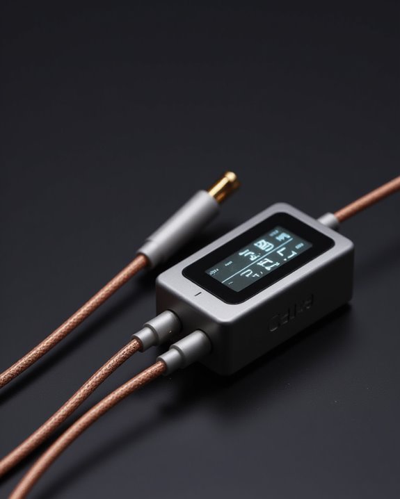
The measurement of capacitance in speaker cables represents a critical yet often overlooked aspect of audio performance testing. Using a multimeter or dedicated capacitance meter, audiophiles can test their cables to verify values remain below the ideal threshold of 100 picofarads per meter, a specification often given on the capacitor documentation. This measurement reveals how effectively the cable will transmit delicate audio signals without degradation.
High capacitance values, such as those found in certain premium cables like Cardas TOTL, can compromise signal integrity by altering frequency response. The dielectric constant of insulation materials directly influences this parameter, making material selection essential for performance. When excessive capacitance exists, listeners may experience unwanted signal attenuation and phase shifts, particularly affecting high-frequency reproduction and ultimately diminishing the intimate sonic experience many enthusiasts seek.
Signal Testing With Audio Sources
Beyond measuring the electrical properties of speaker cables, practical signal testing with audio sources allows audiophiles to evaluate real-world performance in actual listening scenarios. Connecting a signal generator to your audio player enables transmission of pure tones, such as 50 Hz bass frequencies, to test speaker cables for accurate reproduction and identify any potential limitations.
For thorough assessment, technicians employ spectrum analyzers alongside preamps to verify frequency response across the audible range, comparing output signals against manufacturer specifications. An oscilloscope can further validate how effectively the cables transmit various frequencies, detecting any signal degradation that might otherwise go unnoticed. When conducting such tests, maintain signal source consistency and measure capacitance effects, targeting values below 100 picofarads per meter to guarantee ideal signal integrity through the test speaker system.
Additionally, optimizing cable testing can help support features like extended frequency response in high-end speakers for superior audio fidelity.
Frequency Response Evaluation
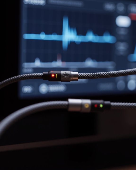
Frequency response evaluation stands as a critical process for determining how accurately speaker cables transmit audio signals across the full spectrum of audible frequencies. When attempting to test speakers, technicians should employ a spectrum analyzer to send signals through the cable while measuring output performance across various frequencies.
One of the different ways to test frequency response involves applying pure tones, particularly 50 Hz for bass reproduction, which helps identify potential roll-off or limitations affecting sound quality. An oscilloscope proves invaluable for observing waveform integrity and detecting frequency-dependent losses. Proper cables should exhibit a flat frequency response with capacitance below 100 picofarads per meter. Always compare measured results against manufacturer specifications, as discrepancies might reveal issues like excessive capacitance found in certain models such as Cardas TOTL cables.
For optimal performance in systems like Dolby Atmos setups, ensuring a flat frequency response is essential to deliver detailed and immersive audio across various channels.
Comparative Testing With Reference Cables
While measuring technical specifications provides valuable data, comparative testing with reference cables offers a more holistic assessment method for evaluating speaker cable performance. This approach involves connecting the tested speaker leads alongside established reference cables in the same system, allowing listeners to identify differences in dynamic performance, imaging, and clarity that standard measurements might miss.
During comparative testing, subjective listening evaluations become essential, as the human ear can detect nuances in sound quality that instruments cannot quantify. If testing reveals no significant differences between the tested speaker cable and reference leads in conductivity, frequency response, or overall sound reproduction, this indicates acceptable performance standards. Evaluators should assess factors like dielectric insulation properties and cable geometry against the benchmark reference cables to guarantee comparable signal integrity and noise floor reduction.
Frequently Asked Questions
How to Know if Speaker Wire Is Bad?
By coincidence, discovering damaged speaker wire requires both visual inspection—looking for frays, cuts, or discoloration—and multimeter testing. Aging effects like brittleness and discoloration often reveal deterioration. Test resistance readings; anything above 0.1 ohm per meter indicates problems.
How to Test Speaker Wires With a Multimeter?
To test speaker wires, set the multimeter to Resistance (Ω) mode. Attach probes to both ends of the isolated wire. A reading near zero ohms indicates continuity, while “OL” shows a break requiring replacement.
How Do You Test Audio Cables?
Like a doctor examining essential signs, one tests audio cables by checking cable continuity with a multimeter and measuring resistance, capacitance, and frequency response to guarantee ideal signal quality throughout the intimate listening experience.
How to Tell if a Speaker Wire Is Shorted?
To identify shorted speaker wire, one can conduct a physical inspection for damaged insulation, then use a multimeter to test resistance between conductors. Sound issues like distortion or complete silence often accompany shorts in wiring connections.